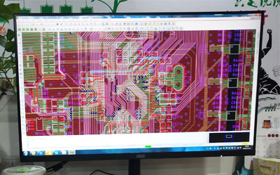
PCB is a widely used product, which is used in almost all electronic and electrical equipment, such as mobile phones, computers, automobiles, remote controls, etc. In the pre-production PCB design, the routing and layout of components is critical. So what are the basic rules for PCB component routing and layout?

PCB Component Routing Basic Rules
1. It is forbidden to arrange the wiring area within ≤1mm from the edge of the PCB board and within 1mm around the mounting hole;
2. The power cord should be as wide as possible and should not be less than 18 mils; the signal line width should not be less than 12 mil; the cpu entry and exit line should not be less than 10 mil or 8mil; the line spacing is not less than 10 mil;
3. Original via is not less than 30 mil;
4. Dual in line: Pad is 60 mil, aperture is 40 mil;
1/4W resistance: 51*55 mil (0805 surface mount); when inserted, the pad is 62 mil and the aperture is 42 mil.
RBD: 51*55 mil (0805 surface mount); when inserted, the pad is 50 mil and the aperture is 28 mil.
5. Please note that the power and ground wire should be as radial as possible, and the loopback traces should not appear on the signal wires.
PCB Component Layout Basic Rules
1. According to the circuit module layout, the related circuit that realizes the same function is called a module. The components in the circuit module should use a centralized rule, and the digital circuit is separated from the analog circuit.
2. Do not place components, screws, etc. within 1.27mm around the non-mounting holes such as location holes and standard holes. Do not place components within the range of 3.5mm (for M2.5) and 4mm (for M3) around the mounting hole;
3. Avoid placing through holes under the components such as the horizontal resistors,inductor inserts, and electrolytic capacitors to avoid short circuits between the vias after wave soldering and the component housing;
4. The distance between the outer side of the component and the edge of the board is 5mm;
5. The outer side of the mounting member is spaced apart from the outer side of the adjacent member by more than 2 mm;
6. Metal housing components, metal parts, such as shielded boxes and the like, cannot be in contact with other components, and should not be in close contact with the printed wiring or pads. Their spacing should be greater than 2 mm. The location hole on the PCB, the fastener mounting hole, the outer side of the elliptical hole and the distance of the other square holes from the edge of the PCB is greater than 3 mm;
7. The heating element cannot be in close proximity to the wire and the thermal element. The high-heat device should be evenly distributed;
8. The power outlet should be placed around the printed circuit board as much as possible. The power outlet and the bus bar terminal connected to it should be arranged on the same side. In particular, care should be taken not to place power outlets and other solder connectors between the connectors to facilitate soldering and power cord design for these receptacles and connectors. The spacing between the power outlet and the soldered connector should be considered to facilitate the insertion and removal of the power plug;
9. Arrangement of other components:
All IC components must be aligned on one side, and the polarity of the polar components should be clearly marked. The polarity on the same printed circuit board shall not exceed two directions. When two directions appear, the two directions should are perpendicular;
10. Board layout should be properly dense. When the density difference is too large, the mesh copper foil should be filled, and the mesh is larger than 8 mils or 0.2 mm;
11. There should be no through holes on the paster pads to avoid solder joint loss and solder joints. Important signal lines are not allowed to pass between the socket feet;
12. The patches are aligned on one side, the characters are in the same direction, and the packaging orientation is the same;
13. Polarized devices should be as uniform as possible in the direction indicated by the polarity on the same board.
Regarding the basic rules of PCB wiring&layout, the above content can be used for reference. The routing and layout of a single-layer PCB is very simple, while the routing and layout of a multi-layer PCB is much more complicated.