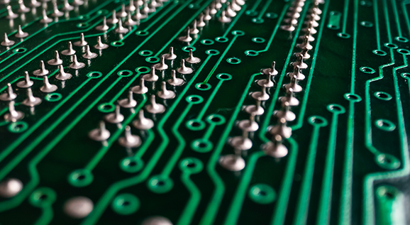
In electric vehicles, the main function of the charging system is to convert an external power source, such as the alternating current (AC) provided by a charging stations, into direct current (DC) suitable for storage in the electric vehicle’s battery pack, while ensuring the safety and efficiency of the charging process. This management of this process is achieved through its internally mounted PCB, which integrates various electronic components and control circuits.

The Key Role of PCBs
1. Power Conversion and Management
1) The charging system PCB usually includes power conversion circuits, which are mainly used to convert AC into DC. The conversion process needs to be efficient and precise to reduce energy losses and the risk of overheating.
2) The charging system PCB plays an important role in the power distribution link. It ensures that the charging current and voltage are always within the acceptable range of the battery, avoiding damage to battery performance due to overcharging or discharging.
2. Communication and Control
1) The charging system PCB not only has to handle the power but also manages the communication of the charging protocol. For example, the charging pile and the car need to exchange data through a communication protocol (such as the CAN bus), and the microcontroller on the PCB is responsible for handling these communications to ensure the smooth charging process.
2) PCB can integrate the data of Battery Management System (BMS) to realize real-time monitoring of battery status and adjustment of charging process, thus ensuring the safety and service life of the battery.
3. Thermal Management
During high-power charging, the PCB needs to process a large amount of electrical energy, which can easily generates a lot of heat. Therefore, thermal management functions are usually integrated into PCB design, such as using heat sinks, thermally conductive materials, or forced air cooling systems to protect circuit components and ensure system stability.
4. Protection Mechanisms
The PCB is also equipped with various protection circuits, such as overcurrent protection, overvoltage protection and short circuit protection. These protection circuits can quickly cut off power when abnormal conditions occur to prevent damage to the battery or other equipment.
Application of PCB in Different Charging Modes
PCBs in electric vehicle charging systems have different applications in different charging modes:
1. Slow Charging (AC Charging)
In slow charge mode, the PCB manages the conversion of AC to DC and controls the current and voltage to ensure slow and safe charging of the battery.
2. Fast Charging (DC Charging)
In fast charging mode, the PCB needs to withstand and handle higher current and voltage in order to quickly transfer electrical energy to the battery. In this case, the heat dissipation and protection functions of PCB are particularly important.
Future Development
With the development of electric vehicle technology, charging system PCBs will become more intelligent and efficient. For example, future PCBs may integrate more intelligent sensors and AI algorithms to further optimize the charging process and extend the battery life.
HoYoGo is an international, professional and reliable automotive PCB manufacturer with a high level of automation and dedicated automotive production lines, automotive PCB account for 49%. Our production strictly follows the high-quality system and is certified by ISO9001, ISO14001, ISO13485 and TS16949. All products strictly follow the acceptance standards of IPC-A-600-H and IPC-6012. If you have related PCB needs, please feel free to send us your inquiries.